By Lowell Christensen, Consultant | Lowell Christensen LLC
In this case study we will compare two types of permanent magnet brushless motors for a medium size overhead fan used in agricultural types of applications. The comparison will be done on the magnetic circuit portion of the motors only so the only volumes and weights compared will be the magnetic circuit parts including the magnet, back iron, lamination and copper wire.
After reviewing the application, it was determined that the parameters of the motor for this application would need to be for a motor voltage constant of 1,000 volts per KRPM and a maximum resistance of 5 ohms. The power requirement of the fan is 1.0HP at a maximum speed of 600 rpm. The outer and inner rotation motors will start with a 12 inch OD design and then decrease the outer diameter to an 8 inch diameter. The length of the motor and motor winding will be increased as the diameter decreases to maintain a constant voltage constant and a constant winding resistance. This will result in a constant power capability in the motor as the diameter and length changes. The ratio of the lamination inner diameter to the outer diameter was held constant at 0.7 to set a constant parameter for varying the motor sizes in diameter and length. This ratio of 0.7 will keep a good slot depth thru the diameter range used and keep the ID of the magnetic circuit large enough to get the size of bearings needed in the ID of the magnetic circuit.
Other parameters that will stay the same in both designs are that the airgap flux density which will stay at 8.5 KG. The wire fill and iron flux density will also stay the same for both designs. The procedure of changing both types of designs was to change OD, then determine the ID using the ratio of the lamination ID to OD. The motor length was then increased until the resistance reached the maximum resistance value at a voltage constant value of 1000. This was done for the outer diameter range of 12 inches to 8 inches in diameter in 1 inch increments. The results were plotted and are discussed below.
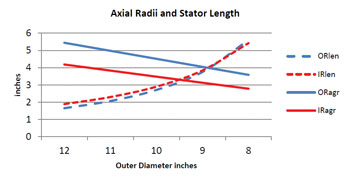 Figure 1 shows the impact of the motor length increasing as the OD decreased in value while keeping the motor output power constant. Also shown is the effect of the mean air gap radius. Since we are keeping the lamination ID to OD ratio the same, the ID radius will be very close for both motor types and is not shown. The motor airgap radius will have a linear decrease in value and a slope very close to the outer radius slope. The outer rotation motor airgap will have a larger radius and is close to the outer radius of the motor while the inner rotation version has it near the ID of the motor and is lower on the curve. The length increase is exponential as the diameter decreases. This would be expected since the resistance was kept constant and as the length increases a higher percentage of the copper wire will be in the slots. This means a higher percentage of the copper is producing toque in the longer motor lengths. The length curve also shows that at the larger diameters, the outer rotation motor length is less than the inner rotation motor length but as the length becomes longer, the curves come together and if the length was longer they would cross over.
 Figure 2 shows the magnetic circuit component weights for the outer rotation style motor. The highest weight component in this style is the laminattion weight. The next highest component was the copper in the winding. The magnet and rotor backiron weights were very small compared to the stator parts and the magnet had the least weight of the components. This would be explained by the fact that the stator is outside the airgap and will have a larger volume in this motor. The rotor is inside the airgap and will have a small volume. The lamination weight started flat but increased exponentially. The copper weight started decreasing exponentially and then started to flatten out at the longer motor lengths.
 Figure 3 shows the same curve for the outer rotation style motor. The magnet weight is the smallest component of the two motor styles. The lamination and copper are still the highest component weight but the rotor weight has caught up to the copper weight. The magnet weight is higher than for the inner rotation motor but is still a small part of the total weight. The vertical scales were kept the same for Figures 2 and 3 so that the weight contributions could easily be seen. The lamination and copper weights still had the same shapes but the changes in values are not as exaggerated as in the inner rotation motor.
The magnet, iron and lamination components have an exponentially increasing weight in both motor types. This would be expected since the length was increasing exponentially. The copper wire weight decreases exponentially. This would be because as the motor length increases the percentage of copper wire in the lamination slot increases and less copper wasted in the end turns. The copper weight for the outer rotation motor is a lot less than for the outer rotation motor since the stator is located inside the airgap. The amount of copper weight is a lot higher in the inner rotation motor and decreases in weight at a lot higher rate than the in the outer rotation motor. This again would be due to the larger volume of copper in the stator located outside the airgap.
 Figure 4 shows the volume and weight comparisons of the magnetic circuits of the two motor design styles. This volume and weight is for the magnetic circuit components and does not include the complete motor. The volume for both motors increases exponentially as the outer diameter decreases and the length increases. This would be expected since the length was increasing exponentially for both designs. Also as the diameter gets smaller and the length gets longer the volume starts getting the same for both motor styles. In the parameters for this case study the Inner rotation volume was less than the outer rotation volume. The weight curves in the case study range have a different shape for the two motor styles. The weight for the outer rotation motor is starting flat and then increasing exponentially. The weight for the inner rotation motor is decreasing at the start and then flattening out and increasing exponentially at the longer lengths. This can be explained by looking at the copper and lamination weights in Figures 2 and 3. For the outer rotation motor the copper weight is decreasing at a small rate and the lamination is increasing at a large rate. Since the decrease is smaller than the increase, the result will be an overall increase. For the inner rotation motor the copper wire weight decreases at a high rate so the sum of the two weights will be different. The copper weight is stating at a decreasing exponentially curve which will flatten out at the smaller diameter values. The lamentation weight is starting flat and then increasing exponentially as the diameter is decreasing. The sum of these two conditions will result in an inverse bell curve as is shown in the graph.
The motor length and volume is not a problem in this type of application but weight will be critical. The weight will need to be supported by some overhead mounting system. The magnet weight in the outer rotation was larger but the magnet weight was a small part of the total weight. The lamination weight and the copper magnet wire weight were the two major contributors to the weight. The lamination weights increased exponentially and the copper weights decreased exponentially for both designs. The copper weight amount and decrease was a lot less for the outer rotation motor. The inner rotation motor had a larger impact of decreasing copper weight as the diameter decreased. For the outer rotation motor both the weight and volume increased exponentially as the diameter was decreased and the length increased. This would show that for this design the shorter length and larger diameter type of design would be the best design. For the inner rotation motor the weight was an inverse bell curve.
Another factor that would affect weight is that the inner rotation motor will need a hub that will attach to the motor shaft and to the fan blades. The outer rotation motor can have the blades attached directly to the outer rotating housing. The higher inertia of the outer rotation motor will also help in the inertia matching of the system. The outer rotation motor is the design chosen for the large fan motor diameter in the range used in this case study. The diameter chosen was a. 10.5 inch outer diameter. This gave the longest stack length while the weight curves were just beginning to rise.
 About the Author
Lowell Christensen is currently a Founder and Vice President of Engineering for TruTech Specialty Motors. Prior to Working at TruTech Specialty Motors, Lowell was working as a Permanent Magnet Motor Design Consultant. Mr. Christensen has a Bachelor of Arts Degree in Physics and Mathematics from Mankato State University and a Bachelor of Science in Electrical Engineering from the University of Minnesota. Mr. Christensen had worked as Director of Engineering at MCG Inc form August 1992 to 2008. Prior to MCG Mr. Christensen worked as Motor Engineering Manager at ElectroCraft Corporation from 1972 to 1978. Prior to ElectroCraft, Prior to ElectroCraft, Mr. Christensen worked at Control Data Corp from 1972 to 1978 as a Motor Design Engineer at Cedar Engineering Division and as a Project Engineer in the Aerospace division. Lowell can be reached at lchristensen@trutechmotors.com.