By Amandeep Bal, Ph.D., Integrated Engineering Software
Market need
Eddy current testing (ECT) is a non-destructive (NDT) testing technique widely used in magnetic sensors to check the integrity of electrically conducting parts and notably to detect flaws. This sensitive technique can locate tight cracks of various types of surface on both non-ferromagnetic and ferromagnetic materials. The factors that are driving this market are advancements in eddy testing technologies and this has encouraged customers to adopt it. The constant demand from power generation, manufacturing, and aerospace sectors have resulted in high adoption of this technique across the world. Stringent regulations related to quality control and periodic inspections laid down by various governments, along with user-friendly software and continuous advancements in automation sectors, are key drivers for the growth of the eddy current and inspection market. S
Scenario and objective
Integrated Engineering Software (IES) is an industry leader to provide user-friendly software programs for various electromagnetic applications. IES’s software program Faraday is a 3D time-harmonic eddy current field solver that gives the advantage to meet ECT challenges head on.
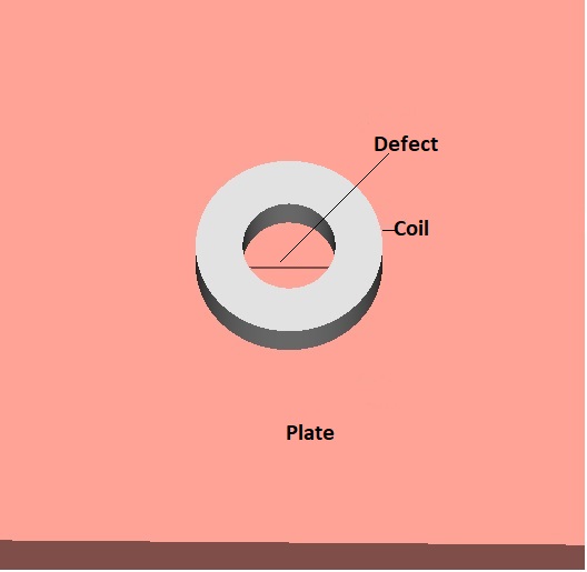
ECT technology uses a time-varying magnetic field, generated by an excitation coil with a sinusoidal or transient current regime, to induce eddy currents in the material. In this article, most popular eddy current nondestructive testing Benchmark problem TEAM Workshop Problem #15-1 * is validated in version 10.1 of Faraday. The scenario involves a circular air-cored coil scanned parallel to the x-axis, along the length of a rectangular slot in an aluminum alloy plate. The image can be seen in Fig. 1. The objective is to compute the change in the inductance and resistance of the driving-point impedance of the coil (compared to its value over an unflawed portion of the plate) as a function of coil position, and compare the computed results to the experimental results. Both the frequency and the coil lift-off are fixed. Three different approaches in the Faraday v 10.1 program are followed to solve this problem. First approach is to set the solver in “fields mode”, second approach is to set the solver in “circuit parameters mode”, and third approach is to use “coils and windings” feature to simulate coils. In “fields” mode, the “Analysis” menu will display bulk results such as energy, total charge, etc. including mechanical calculations such as force and torque while in circuit parameters mode, menu will display Capacitance/ Inductance, etc. The “coils and windings” feature in the software is useful to design coils and windings in electric motors and can easily overcome challenges like analyzing resistive and inductive requirements, eddy currents and proximity effects.
Integrated Engineering Software (IES) is an industry leader to provide user-friendly software programs for various electromagnetic applications. IES’s software program Faraday is a 3D time-harmonic eddy current field solver that gives the advantage to meet ECT challenges head on.
ECT technology uses a time-varying magnetic field, generated by an excitation coil with a sinusoidal or transient current regime, to induce eddy currents in the material. In this article, the most popular eddy current nondestructive testing benchmark problem, TEAM Workshop Problem #15-1*,is validated in version 10.1 of Faraday. The scenario involves a circular air-cored coil scanned parallel to the x-axis, along the length of a rectangular slot in an aluminum alloy plate. The image can be seen in Fig. 1. The objective is to compute the change in the inductance and resistance of the driving-point impedance of the coil (compared to its value over an unflawed portion of the plate) as a function of coil position, and compare the computed results to the experimental results. Both the frequency and the coil lift-off are fixed. Three different approaches in the Faraday v 10.1 program are followed to solve this problem. First approach is to set the solver in “fields mode”, second approach is to set the solver in “circuit parameters mode”, and third approach is to use “coils and windings” feature to simulate coils. In “fields” mode, the “Analysis” menu will display bulk results such as energy, total charge, etc. including mechanical calculations such as force and torque while in circuit parameters mode, menu will display Capacitance/ Inductance, etc. The “coils and windings” feature in the software is useful to design coils and windings in electric motors and can easily overcome challenges like analyzing resistive and inductive requirements, eddy currents and proximity effects.
Geometry
he input parameters for the model are taken from TEAM Workshop Problem #15-1. The description does not mention how big the plate used in the measurement is. Therefore, in order to see the effect of edge of the model on results, two different sizes of plates with thickness 12.22 mm are studied. Both sizes are big enough so that the coil does not reach the edge. The length of defect parameters in plates is 12.60 mm, depth is 5.00 mm, and width is 0.28 mm. The inner radius of coil is 6.15 mm, outer radius is 12.4 mm, length is 6.15 mm, number of turns in coil are 3790 and lift off is 0.88 mm. Only a half model is produced for first two approaches (fields and circuit parameters mode) because geometry is symmetric about the center for all coil locations and the number of unknowns required to solve the model could be reduced (hence reducing the solution time).
Setting up Physics in the software
In Faraday’s Physics Global Setup menu, circuit parameters/fields mode is setup with frequency as 900 Hz. In the Material Table, a conductor with conductivity 3.06×10⁷ S/m is created and then applied to the plate. Symmetry of the model is set up in Symmetry and Periodicity Setup. Volume Current of 3790 A is introduced in the coil. Coil is assigned as Volume Conductor #1 and volume Conductor #1 is assigned 1 A (per turn – together with the total current makes a 3790-turn coil).
Setting up Solvers in the software
Faraday has both finite element method (FEM) and a Boundary Element Method (BEM) solver available. FEM provides sufficient accuracy for engineering purposes, and many problems are by their nature inherently closed region. BEM not only provides the most accurate numerical field solutions but is also the method of choice for problems involving the modeling of space around the device: that is what we call “large open regions”.
Faraday has both finite element method (FEM) and a Boundary Element Method (BEM) solver available. FEM provides sufficient accuracy for engineering purposes, and many problems are by their nature inherently closed region. BEM not only provides the most accurate numerical field solutions but is also the method of choice for problems involving the modeling of space around the device: that is what we call “large open regions”.
Since this is an open region problem, and furthermore there are no nonlinear materials, the BEM solver is expected to be superior and is applied to solve this problem in fields/circuit parameters mode. Since the “coils and windings” feature of software works with FEM solver, so FEM is applied for the solution while using this feature.
Since this is an open region problem, and furthermore there are no nonlinear materials, the BEM solver is expected to be superior and is applied to solve this problem in fields/circuit parameters mode. Since the “coils and windings” feature of software works with FEM solver, so FEM is applied for the solution while using this feature.
Generating an element distribution with the Automatic commands
The “Automatic All” commands in the software automatically generate the specific type of 2D or 3D elements in all surfaces (or volumes as appropriate) that require them based on physical assignments to the geometry. In this problem, the plate requires 2D elements and the coil requires 3D elements. A quick solution is acquired by using “Automatic All” to instruct the mesh generator to decide which parts of the model require 2D or 3D elements.
Parametric Analysis
Faraday has “Parametric Analysis” to solve a series of models that are variations of a single basic design. The model variations are created during the course of the run according to the range of parameters defined. To solve current problem, a parametric analysis is setup to move the coil outwards automatically from the center in 0.5 mm steps. The objective is to compute the change in the inductance and resistance of the driving-point impedance of the coil (compared to its value over an unflawed portion of the plate) as a function of coil position and compare the computed results to the experimental results. The computed and experimental results are to be compared by plotting the magnitude of each versus coil-center position. Unflawed models are also solved to calculate inductance and resistance through similar parametric set up.
Results
Circuit parameters mode
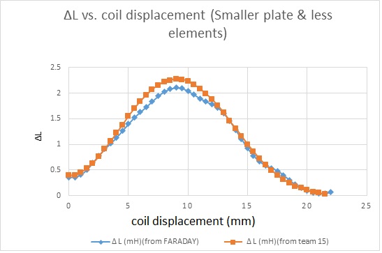
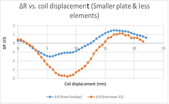
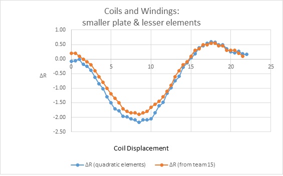
Figure two and three shows change in inductance (∆L- mH) and change in resistance (∆R-ohm) for smaller plate with lesser elements. The orange points are the measure data from T.E.A.M 15 and the blue curves are the Faraday 10.1 results. Clearly, the L results are more accurate than the R results. This is because the calculation made by Faraday gives the impedance, and then divides it into real and imaginary parts. In this problem, the phase is approximately 89o, so the relative error is much higher in the real part (resistance) than in the imaginary part (inductance).
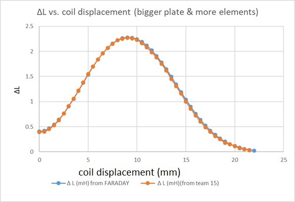
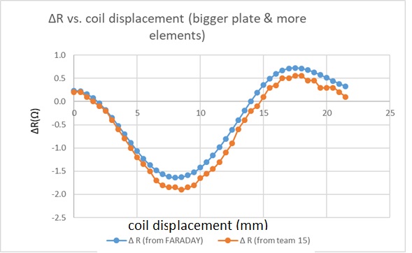
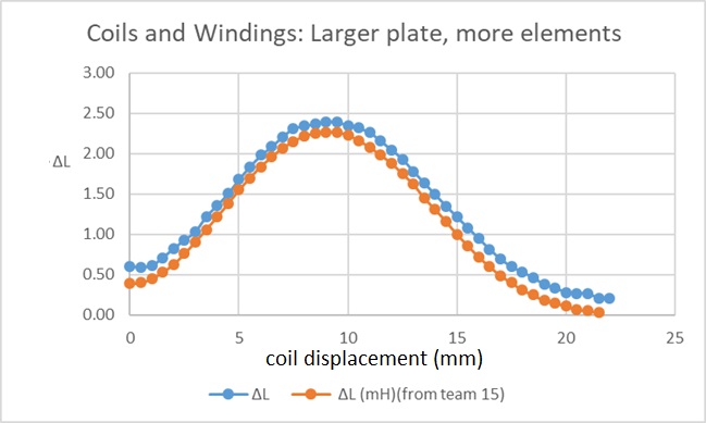
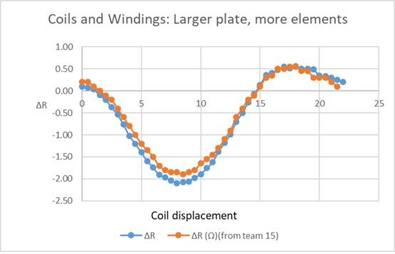
In order to see the effect of edge of the model and element density, the plate size is increased by 6 mm and the element density is increased from 1700 to 2300 triangular elements and from 100 to 120 brick elements on plate and coil respectively. The results are shown in figure four and five and are more accurate as compared to results in figure two and three.
Fields Mode
Although circuit parameters mode seems the obvious choice for solving this problem, the model is also solved in Fields mode. From Faraday’s Physics global set up, fields mode is selected to solve the problem. The results obtained are not much different from circuit parameters mode.
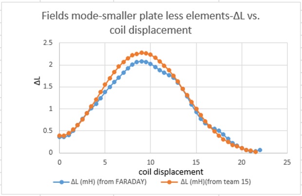
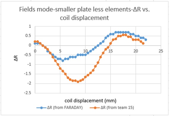
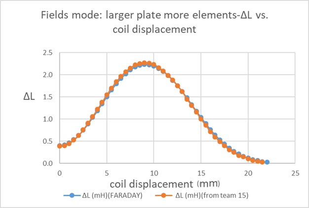
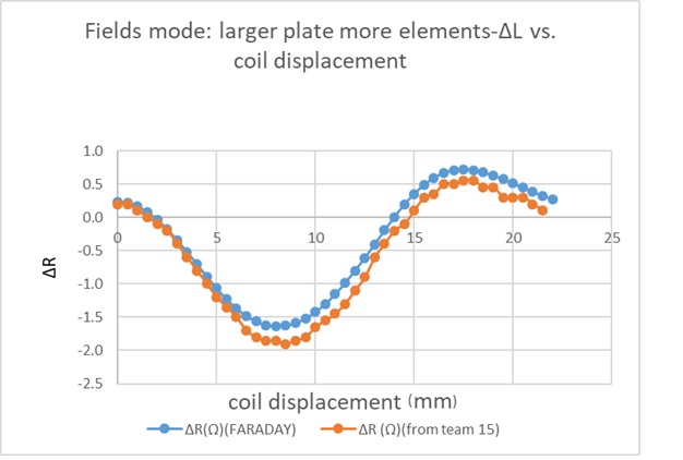
Since there is only one power source in this model, the real part of the power loss in the block must also be the real power loss pulled from that source. Hence, a power loss calculation on the plate enables us to compute the resistance seen by the coil by using formula P=I2 R. The plots below show results from a Fields mode solution with 1 A at a phase of 0 (to simplify calculations) in the coil. L is recorded from flux linkage using formula L=N*Φ/I and R is recorded from “Power loss”. Figure 6-9 shows change in inductance and resistance values in the model with and without defect. Again, the bigger plate with more elements shows more consistent results with measured data as compared to the smaller plate with lesser elements.
Using Coils and Windings Editor
Faraday has a specialized feature “Coils and Windings” to simulate motors and generators because of the large number of coils and rotational transients and highly nonlinear switching sources and loads involved in them. This feature defines a set of coils wound onto the device, number of turns in a defined area and multi-phase systems with delta/star connections. This feature can easily overcome challenges like analyzing resistive and inductive requirements, eddy currents and proximity effects, coupled series and parallel connections with additional circuit elements. It identifies a set of coils, attach them with the right polarity and assign them to a winding with the required source while designing motors, transformers, sensors and many other devices.
This feature works with Finite Element Method and is applied to simulate this problem to see the consistency of results as compared to other approaches discussed above. Full model is used for this study. To set up this feature:
- “Coil Type properties” are edited from “Coils and windings” dialog from “Physics” menu
- Coil geometry is selected from “Set Coil Geometry” and proper current direction is selected from “Toggle Current Direction”.
- “Windings” are specified with current source of 1 Ampere and phase zero.
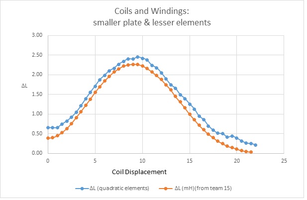
To solve the model a parametric is setup to automatically move the coil outwards from the center in 0.5 mm steps and to record L & R at each position. L and Rare recorded from “Analysis” menu. L is recorded from flux linkage using formula L=N*Φ/I and R is recorded from “Power loss” by using formula P=I2 R where I=1 and N= 3790. Figures 10-13 show change in inductance and resistance values in the small and large plate models. The blue points are the Faraday 10.1 results and the orange curves are measured data. The results showed better results for larger plate model. Hence, we can conclude that either we use field mode or circuit parameters mode or coils & winding feature, the results of larger plate with more elements are better.
Conclusion
Simulation results on most popular eddy current nondestructive testing Benchmark problem TEAM Workshop Problem #15-1 is validated in Integrated Engineering Software’s program, Faraday v10.1. Three different approaches are used for the study, which concludes that a user wishing to improve on the results should make the plate larger with more element density. In general, the higher the element density, and the more closely the geometry matches the real geometry, the better the result will be – but the longer it will take to obtain it. This study proves that the Faraday software is very effective for designing nondestructive testing equipment for magnetic sensors.
*TEAM Workshop Problem #15-1: http://www.compumag.org/jsite/images/stories/TEAM/problem15.pdf

About The Author: Amandeep Bal, Ph.D., is the Testing and Benchmarking Engineer for Integrated Engineering Software based in Winnipeg, Canada. Integrated Engineering Software develops simulation software programs that analyze a full spectrum of physical problems.
For more information, visit: https://www.integratedsoft.com