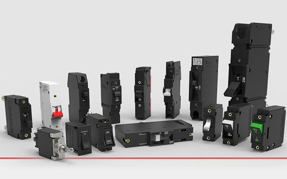
Magnetic circuit breakers are a long-established, widely used product that can easily be taken for granted. But design refinements and advancements continue relentlessly to meet the demands of product developers. You might be surprised at their intricacies — well explained by Carling Technologies, a leading maker of switches and circuit protection products.
Hydraulic-magnetic circuit breakers provide highly precise, reliable and cost-effective solutions to most design challenges. Notably temperature stable because they are not appreciably affected by changes in ambient temperature, their overcurrent sensing mechanism reacts only to changes of current in the circuit being protected. This article highlights Carling’s presentation on “Trip Time Delay” and two recent product developments.
Basically, a circuit breaker is an electrical switch that automatically opens a circuit when certain electrical conditions are met. In general, circuit breakers open (trip) when the electrical current through a sensing device exceeds a pre-established current rating. Carling. Technologies’ manufactures circuit breakers with a hydraulic/magnetic tripping element. Using the example of the most common circuit configuration, “Series Trip, Carling explains what makes hydraulic/magnetic circuit breakers trip, and how trip time delays are obtained.
What Makes a Magnetic Circuit Breaker Trip?
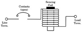
The hydraulic/magnetic circuit breaker “Series Trip” configuration consists of current sensing coil connected in series with a set of contacts. (Figure 1)
Inside the coil is a non-magnetic delay tube housing a spring-biased, moving magnetic core. An armature links the contacts to the coil mechanism, which functions as an electromagnet. When the contacts are open, there is no current flow through the circuit breaker, and the coil develops no electromagnetic energy. When the contacts are closed, current flow begins. (Figure 2)
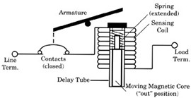
As the normal operating or “rated” current flows through the sensing coil, a magnetic field is created around that coil. When the current flow increases, the strength of the magnetic field increases, drawing the spring-biased, movable magnetic core toward the pole piece. As the core moves inward, the efficiency of the magnetic circuit is increased, creating an even greater electromagnetic force. When the core is fully “in”, maximum electromagnetic force is attained. The armature is attracted to the pole piece, unlatching a trip mechanism thereby opening the contacts.(Figure 3)
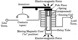
Under short circuit conditions, the resultant increase in electromagnetic energy is so rapid, that the armature is attracted without core movement, allowing the breaker to trip without induced delay. This is called “instantaneous trip”. It is a safety feature that results in a very fast trip response when needed most. (Figure 4)
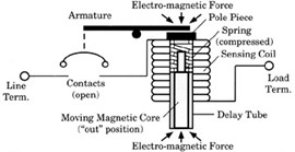
How Various Time Delays are Obtained
The trip time delay is the length of time it takes for the moving metal core inside the current sensing coil to move to the fully “in” position, thereby tripping the circuit breaker. The time delay should be long enough to avoid nuisance tripping caused by harmless transients, yet fast enough to open the circuit when a hazard exists.
If the delay tube is filled with air, the core will move rather quickly, and the breaker will trip quickly. This is characteristic of the Ultrashort trip time delay. Solid state devices, which cannot tolerate even short periods of current overload, should use the Instantaneous trip time delay, which have no intentional time delay.
When the delay tube is filled with a light viscosity, temperature stable fluid, the core’s travel to the full “in” position will be intentionally delayed. This results in the slightly longer Medium trip time delays that are used from general purpose applications. (Figure 5).
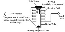
When a heavy viscosity fluid is used, the result will be a very Long trip time delay. These delays are commonly used in motor applications to minimize the potential for nuisance tripping during lengthy motor start-ups.
By use of magnetic shunt plates within the magnetic circuit, it is possible to divert the magnetic flux, thereby resulting in a higher inrush withstanding capability. These High Inrush trip time delays disregard short duration, high pulse surges (typically 8 ms or less and up to 25x rated current) characteristic of transformers, switching power supplies and capacitive loads.
Hydraulic delay protectors have the added advantage of tripping slightly sooner when operating in higher temperature conditions and slightly longer in lower temperature conditions. This characteristic mirrors the protection needs in most applications. Note that the time delay for tripping changes, but the current required to trip the breaker does not change.
Delay Curves
Each trip time delay type can be graphed to display trip time delay curves. These curves represent the relationship between the percent of rated current and the trip time in seconds. See the example below.
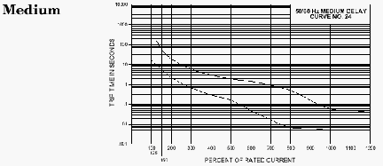
Recently introduced hydraulic-magnetic circuit breakers
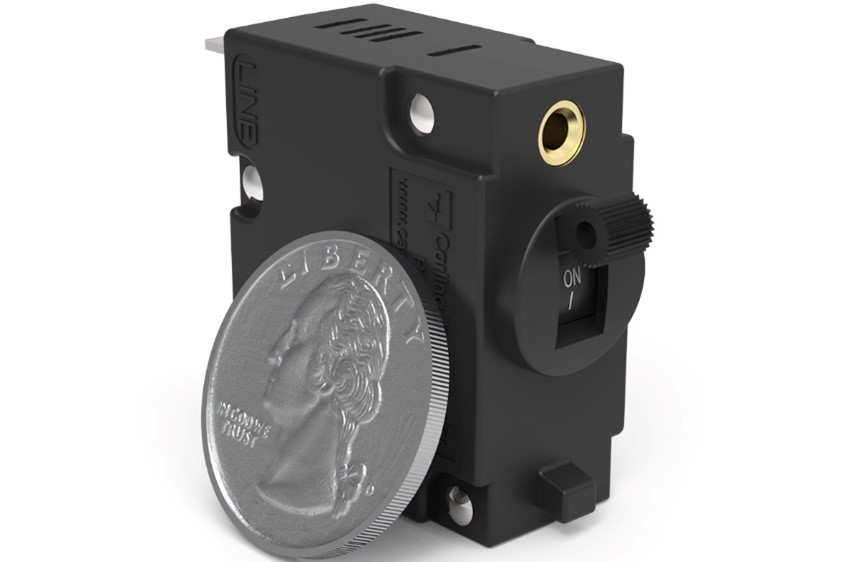
The K-Series is a micro-sized single-pole hydraulic-magnetic circuit breaker that can be configured for AC or DC applications with a maximum voltage rating of 65 or 80 VDC or 250 VAC. It is available with printed circuit board assembly (PCBA), push-on tab, or screw terminals as well as instantaneous, short, and medium time-delay options. It is designed to be an ideal solution for today’s confined and crowded datacom and telecom rack systems and 5G devices.
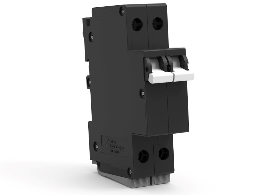
The R-Series hydraulic-magnetic circuit breaker, introduced in September 2023, combines maximum protection with ease of use, configured for DIN rail mounting with no hardware or front panel cutout requirements. Applications include datacom/telecom, renewable energy, industrial automation and railway.
Located in Plainville, Connecticut, Carling is a Littelfuse brand that was acquired by Littelfuse in 2021. For more info and to access the full presentation on Trip Time Delay, see www.carlingtech.com.

