By Chris Riley, Technology Manager • Vector Fields Software, Cobham Technical Services
Superconducting magnets and magnetic systems are making an impact all over the world. Magnetic resonance imaging (MRI) has become the main medical diagnostic visualization tool for soft tissue, and we have all become used to seeing detailed scans of sections through the human brain and other vital organs and joints. The only realistic technology for whole body scanners, which require a highly homogeneous field region of 2 Tesla or more in a 0.5 m diameter sphere, is superconducting magnets. The same technology is also used for nuclear magnetic resonance (NMR) systems, which make extensive use of superconducting magnets to achieve much higher fields, albeit with a smaller homogeneous region, for material analysis.
Keeping particles on track as they approach the speed of light in the Large Hadron Collider and other particle accelerators can only be attained using very powerful superconducting magnets. The advent of high temperature superconductors (HTS) has also reinvigorated the interest in superconducting windings to replace lossy copper ones in synchronous motors and generators, with the added bonus that substantial physical size reduction can be achieved for a particular power rating. However, superconducting materials are still relatively expensive and “right first time” is an important paradigm. Software design and simulation tools play a vital role in achieving this.
In particular, the simulation of superconducting quench (the transition from the superconducting to the normal state) is a critical part of the design process. Superconducting magnets must be designed to withstand quenches, whether these are anticipated, such as occur during training due to micro movements of the windings, or from unexpected events such as earth tremors. Failure to withstand quench can be catastrophic with considerable mechanical damage to the magnet and cryogenics. Safe dissipation of the very large stored energy in the magnet following a quench requires sophisticated protection circuitry to also be an integral part of the magnet design. Magnet energies are increasing all the time, with HTS inserts extending the range of field that can be achieved beyond the limits for low temperature superconductor (LTS) magnets, because HTS is able to operate at higher field intensity. Accurate characterization of HTS and LTS materials at temperatures approaching absolute zero is also vital for quench simulation. Material properties can change by an order of magnitude within a few degrees at low temperatures and magneto-resistive effects also become more prominent. Consequently, electromagnetic, circuit, thermal and mechanical behavior must all be addressed simultaneously; a true multi-physics challenge.

To improve the capability of design tools for this demanding application, the UK Technology Strategy Board (under program TP/5/MAT/6/I/H0647B) has supported a collaboration between three of the UK’s leading groups. The project, entitled “Integrated Modelling Package for Designing Advanced HTS Materials Applications (IMPDAHMA)”, was led by Oxford Instruments Nanoscience (OINS), who design and manufacture magnets, in association with University of Southampton Cryogenics Institute, and Cobham Technical Services Vector Fields Software (VF).
Finite element based modelling of superconducting quench, the responsibility of VF, requires simultaneous co-simulation of the thermal, electromagnetic and circuit equations, usually called a multi-physics simulation. Mechanical stress can be adequately calculated as a post-simulation coupled analysis once the maximum forces have been determined. The multi-physics simulation must also include specialist features to identify which finite elements are operating in the superconducting state and which have switched to normal, becoming resistive and producing Ohmic losses.

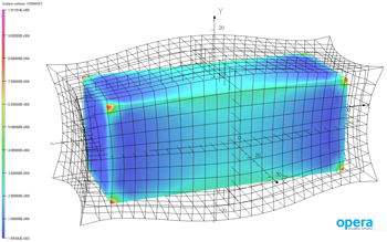
Experience with LTS materials prior to IMPDAHMA [1], [2], [3] identified that accurate representation of the temperature profile “wave-front” associated with the transition from the superconducting to normal state regions of a coil was critical for accurate prediction of currents and voltages in the protection circuitry. Figure 1 shows the temperature distribution during the early part of a typical quench, where the sharp transition between the zone still at cryogenic temperature and the normal zone can be clearly seen. IMPDAHMA developments improved the representation of the wave-front by allowing the mesh in the superconducting coil to be modelled using hexahedral finite elements, as well as using tetrahedral finite elements in other parts of the model. VF coined the term “Mosaic” mesh to refer to a mesh that could include a mixture of element types. Hexahedra allow higher aspect ratio elements in the current flow direction of the coil without compromising accuracy. This can reduce the number of degrees of freedom compared to a tetrahedral mesh or, more probably, allow a more accurate simulation with a similar number. In either case, the speed of the simulation is also improved with hexahedra.

Table 1 shows some example performance results for a test model, while Figure 2 shows the representation of the wave-front with different discretization levels. As can be seen from the 16 and 32 radial element cases in Table 1, hexahedral elements and tetrahedral elements of the same size produce approximately the same number of degrees of freedom (equations), but simulation with hexahedral elements improves simulation time by more than a factor of three. Figure 2 shows that the Mosaic mesh with only eight hexahedral elements in the radial direction captures the shape of the wave-front more precisely than any tetrahedral mesh, while 16 and 32 radial hexahedral meshes are even more accurate.

Hexahedra can only be generated in volumes of the coil with certain structural conditions. Complex shapes such as inter-winding connections or support structure for the coils still require that these volumes are meshed with tetrahedral elements. To allow the transition from hexahedral to tetrahedral elements, prism and pyramid finite elements were also developed in IMPDAHMA, extending the definition of Mosaic. In Table 1, the Mosaic mesh with 8 radial elements is a mixture of hexahedra, pyramids and tetrahedra. The other two Mosaic meshes are composed purely of hexahedra. Figure 3 shows an example Mosaic mesh with a transition between two different sizes of hexahedral element.
One of the other major simulation developments in IMPDAHMA was to integrate the quench simulation with the proprietary design tools used by OINS in their routine design. The interactive Modeller and Post-processor in Opera include a sophisticated scripting language that incorporates declarative program technology and expression analysis [4]. This allowed development of an application specific software environment for magnet design in Opera. The environment directly reads output data files from the OINS design tools to construct finite element models for the quench simulation without manual intervention, supporting a fast throughput of designs and eliminating human error. As well as geometric data, the OINS data contained the necessary electrical and thermal material properties for both the constituent materials of LTS wire and bulk properties for HTS tapes. Much of this data was generated in IMPDAHMA from measurements made by Southampton over a wide range of magnetic, thermal and electrical conditions and, as previously stated, is often highly non-linear at cryogenic temperatures [5]. Representing the coil at individual material level is infeasible for a realistic design simulation, so the scripting constructed the bulk coil material properties from the constituent non-linear tabular data using algebraic constructs [6]. Storage of the complex data for representation of the materials was also addressed by development of a new materials database structure that could also be directly integrated with the finite element model construction tools using the scripting language.

The output data from OINS also contained a description of the protection circuitry, which was automatically translated by the environment to the required structure for co-simulation of the electromagnetic and thermal finite element and the circuit equations. Opera’s inbuilt circuit editing tools were further developed to give graphical representation of the exported circuitry, allowing circuit changes to be made interactively in the finite element model generation tool without having to reconstruct the entire model again from the OINS design tools. The output data was also used to construct the control algorithms for the quench protection circuitry with the capability of switching on resistive heaters to other coils in a magnet after quench has been detected in a particular coil. Figure 4 shows the main input dialog for the OINS output data and application specific results generated by the environment, configurable by the designer.

The simulation was validated by a program of testing on representative LTS and LTS/HTS magnets at OINS. These were extensively instrumented allowing voltages and currents of individual winding layers and coils to be recorded during a quench. Figure 5 compares the experimental and simulated voltages for the coils in an LTS magnet with HTS insert, showing that both the magnitude and time profile of the voltages are being accurately calculated. During these tests, Southampton’s extensive accurate materials measurements became important with low temperature magneto-resistive effects in the copper matrix surrounding the LTS filaments playing a significant role.
Developments from IMPDAHMA have been fully integrated into VF’s main design software package, Opera. The improved circuit editor has allowed electrical designers in many disciplines to integrate electromagnetic finite element models with complex power electronic circuits, especially in the area of motor drive systems. Mosaic meshing has also improved accuracy for calculations in thin sheet eddy current structures and very narrow gaps between permanent magnets. A further spin-off has been the inclusion in Opera of a library of DI-BSCCO HTS wire material properties, supplied by Sumitomo Electric.
References
[1] G J C Aird et al, Proc. ICAP Conference, Chamonix, 2006
[2] Eric Sun et al, IEEE Trans. App Superconductivity, Vol. 20, No. 3, Jun. 2010
[3] Eric Sun et al, IEEE Applied Superconductivity Conference, Aug. 2010
[4] C.S. Biddlecombe and C.P. Riley, IEEE Trans. Mag., Vol. 24, No. 1, Jan. 1988
[5] Z. Melhem et al, 20th Magnet Technology Conference, Philadelphia, Aug. 2007
[6] Opera-3d Reference Manual version 14R1, Cobham Technical Services Vector Fields Software, 2011
 About the Author
Chris Riley is Technology Manager for Vector Fields Software in Oxford UK, a business unit of Cobham Technical Services specializing in software for electromagnetic design. He has worked in the field of electromagnetic design for more than 30 years since graduating in electrical engineering from University College, London in 1975. He joined Vector Fields in 1986, after previous positions with GEC Power Engineering, Compeda and Liverpool University. He is primarily concerned with applications of design software, with particular interest in electrical machines, magnetic and electric signatures from naval vessels and superconducting magnets. He is currently serving a second period on the Institution’s executive committee for the Electromagnetics Knowledge and Technology Network. Chris can be reached at chris.riley@cobham.