By John Beigel • MEDER electronic, Inc.
With the advent of new and improved technologies, sensors are expanding dramatically and are finding new requirements across many market segments including telecom, instrumentation, security, medical, automotive, home appliance, marine, consumer products and general purpose. Each of these market segments has unique qualities and requirements, which has further fueled the rapid growth of sensors. Magnetically actuated sensor requirements are especially in demand because more and more applications are calling for the ‘no touching’ aspect of these sensors. Also, the ‘see through’ effect of magnetic fields through all non-ferromagnetic metals and plastics is clearly needed and on the rise, as this allows switching to take place where the magnetic source does not ever come in contact with the sensor. This attribute is a key design-in requirement for many new sensing applications.

Electromechanical (EM) sensors also offer unique sensing attributes. Specifically, they can switch directly and under relatively heavy power loads. They require a direct connection to their spring loaded lever contact (see Figure 1). The EM sensor used to be a very cost effective option, but that is no longer the case as Hall and Reed sensors have expanded and have become very competitive. Also, with more and more sensors needing the ‘no touch’ requirement, this has directly limited some of the EM sensor growth.
Inductive sensors are another technology that uses the ‘no touch’ approach. They use the principle of changing inductance by inserting a metal probe into a coil form. The applications require strict control and cannot be widely used. They are also very expensive.
While there are many sensor technologies available, the most commonly used are the Reed and Hall sensors. This is due to the fact that these technologies are able to fulfill the parameters and requirements of a large number of applications. Below, we will discuss each technology and provide a comparison of them (as well as comparison to EM) in order to guide decisions regarding which type of technology to design in to a new application.
We will also explain how certain applications have been made possible only through these new technologies and their new added features. These features affect size, packaging, added built-in features, improved cost and improved electrical specifications.
The ‘No Touch’ Sensing Approach (Reed and Hall)
There are many applications in which sensors cannot come in contact with the moving member that needs to be sensed.
Here are some examples:
- An assortment of under the hood automotive sensors, one of which measures the brake level fluid. Brake fluid is very corrosive and most materials are destroyed by this fluid when in contact for long periods of time. With this in mind, the sensor is external to the brake fluid reservoir and senses the movement and position of a plastic float riding on the fluid. A magnet is imbedded in the plastic float establishing the communication.
- Rotational monitoring applications: as gas, water and/or electricity are used in the home, a disk located inside their individual meters rotates with increasing speed depending upon the usage. Touching the disk in any way would disrupt its rotation, negating its accuracy. A sensor is used to count the disk revolutions, which is then electronically converted to the volume of gas, water or electricity used.
- Telephone off-hook sensing, along with flip phone sensing: off-hook sensing used a direct mechanical connection. In this case, allowances had to be made with a lever opening in the body of the phone. This opening allowed for spillage to occur that would seep into the sensitive electronic circuits, either corrosively opening or shorting out the voice signals. Going to a no touch sensor, the problem was solved. Here a magnet built into the phone handle and then placed in the holder would activate a reed sensor. This in turn, would give the indication that the phone had been hung up.
- Commercial coffee makers must keep track of their fluid levels, some of which are under pressure and are super heated above 100°C. The sensors need to carefully monitor the position of the fluid and communicate this directly to power loads or the electronics.
- Many medical applications require no touch sensing, such as pacemakers, implantable defibrillators, video camera pills, muscle stimulation, animal tracking, drug dispensing and hearing aids. Many of these applications require the sensor to be enclosed in the body with the electronics. Activating the sensor is done with an external magnet. This allows for transfer of information and/or mode or parameter adjustment.
In addition to the above-mentioned applications, there are many more where it is essentially impossible for the sensor to make direct contact with the sensing element. In addition to the ‘no touch’ requirement, there are many other factors to consider when choosing between a Reed or Hall sensor.
Understanding the Technologies
All of the previous sensing requirements require magnetically driven sensing. Most of the time, either Hall sensors or Reed sensors are used.

Hall Sensors – In 1879, a physicist named Edwin Hall, working at John Hopkins University, discovered this magnetic effect, which is named after him. Essentially, he found that when applying a current to a material with available ‘loose electrons’ in an applied magnetic field, a voltage would develop that was perpendicular to the applied current and the applied magnetic field.
When they were initially produced, the Hall Effect semiconductors were rather large, bulky and expensive. When semiconductor integration processing expanded, about 30 to 40 years ago, Hall’s popularity began to increase. Now, Hall sensors are manufactured in an integration process and their size and cost have both dramatically decreased.
The Hall sensor is generally a three to four leaded device where two of the leads supply the current and one or two leads supply the voltage, depending upon the sharing of a common ground. One negative to the technology is that a current needs to be flowing all the time (see Figure 2). Since many applications are power limited, a chopper circuit has been added to the integration process that interupts the current flow on a continuous high duty cycle basis. This results in an overall reduced use of power. Further detection circuitry needs to be added, but with the integration process, this adds only a small increase in cost. As a magnetic field, such as a magnet, is bought close enough to the Hall sensor, it will begin producing a small voltage in the millivolt range. The closer the magnet is to the Hall sensor the stronger the induced voltage.


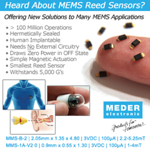
The Reed Sensor – The Reed sensor is a far simpler device. The reed sensor is composed of a hermetically sealed, two leaded reed switch (see Figure 3). The two leads are ferromagnetic and therefore react to each other by closing when confronted by a magnetic field in its sphere of influence. When a magnet is bought close enough to the reed sensor, the contacts will close. When the magnet is withdrawn, the contacts will open. The reed sensor requires no external circuitry and can switch loads directly.

Like Hall sensors, Reed switch technology has also gone the semiconductor manufacturing technology route. Some companies are now offering a micro-machined reed switch (Figure 4). As its name implies, they are extremely small and comparable in size to the newest Hall sensors. However, unlike the Hall sensor, they do not draw any current in the off state.
Both the conventional reed switches and the new micro-machined reeds can be packaged in various sizes to fill customer needs (Figure 5).
Comparing the Technologies on a Parameter Basis
In order for designers to figure out which type of sensor should be used in a given application, it is useful to compare the sensors based on specific parameters. Table 1 provides an efficient method of comparing the various sensors.

Summary
Although there are many other parameters that could be used to compare the different types of sensors, the ones presented represent the key parameters of the technologies. Cost was not considered in the comparisons, as each technology’s prices are competitive with one another.
Each technology offers unique, specific operating characteristics. Designers should compare and contrast the features of each sensor in order to decide which technology is the best choice for use in a particular application. Choosing the wrong technology for a given application can result in wasted time and money and potentially lost customers. In order to assure the best results possible, always work closely with the manufacturer’s engineers and ensure that they understand the details and requirements of your application.
 About the Author
John Beigel received his BS and MS in Physics from the University of Massachusetts Amherst. John worked for EI&S as Engineering Manager from 1972 to 1981; Coto Technology as VP of Marketing and Engineering from 1981 to 1995; Clare Corp as VP of Marketing and Engineering Relay Division from 1995 to 1998; and MEDER electronic Inc. as CEO for North America from 1999 to 2009 before retiring. John is currently consulting for MEDER electronic. In all of the above companies he worked to further the development of reed switch technology.
Published in Summer 2011 Issue

We’ve been trying to figure out how to select reed or hall sensors on the TechXchange forums recently: http://www.digikey.com/techxchange/thread/4193. Thank you so much for the table–it is super helpful in that regard.