By Dr. Zbigniew Piec and Thomas W. Overton
Recent advances in superconductor technology, especially high-temperature superconductors (HTS), have revolutionized industries from defense and transportation to energy, medicine, and basic science. Magnets employing superconducting (SC) material in their windings can achieve significantly higher magnetic fields at much greater efficiencies than those relying on non-SC materials. Superconducting magnets are unique enablers for industrial and science applications such as medical diagnostics, nuclear fusion, and particle accelerators. HTS magnets in particular offer considerable promise for these applications.
Modern SC materials provide high current densities in a wide range of magnetic fields and temperatures. These features are used in SC magnets to produce high fields, reduce magnet size, and lower power consumption. The development of rare-earth barium copper oxide (REBCO) conductor tape, which is an HTS material, offers intriguing possibilities for such magnets with their benefits over low-temperature superconductors (LTS). HTS conductors can either be operated at higher temperature with less current carrying capability, or they can be operated at low temperatures (4-10K) at higher fields than LTS. Though prototype REBCO magnets have been demonstrated, these typically use immersion cooling (placing the coil in a cryogenic bath), which is impractical for many applications.
Research into fusion energy has long been a driver of innovation in magnet technology. General Atomics (GA) has been developing HTS magnets based on REBCO conductor to advance the magnetic fusion energy development program in conjunction with operating the DIII-D National Fusion Facility in San Diego for the U.S. Department of Energy. Magnetic fusion devices require high magnetic fields, and it is believed by the fusion community that HTS magnets could significantly enhance performance characteristics while reducing both the size and cost of fusion devices, potentially including future fusion power plants.
Development
GA’s HTS magnet development takes place at its Magnet Technologies Center (MTC) in San Diego, California. The MTC is a state-of-the-art facility that builds on GA’s 50-year history of developing large and innovative magnets for fusion energy, defense, medical, and other applications. The MTC can perform all stages of LTS magnet design and fabrication for the largest and most powerful SC electromagnets. Over the past several years, the MTC has also successfully expanded their core capabilities in development of HTS magnet technology.
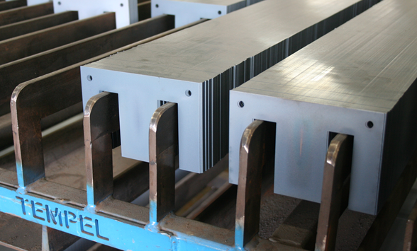
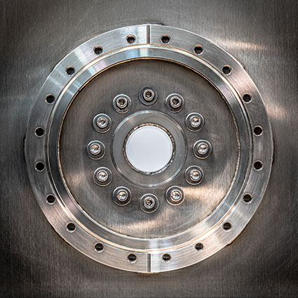
As part of its research into fusion applications, GA engineers have developed a design for a 6 Tesla non-insulated (NI) HTS REBCO-based magnet that uses conductive cooling, rather than immersive cooling methods (i.e., no active cryogens are inside the magnet housing). The first example was completed in 2019 (Figure 1).
This HTS magnet was wound from 500 meters of 12-mm REBCO tape procured from SuperPower, a New York–based supplier of superconducting tape and wire. At the start of the project, the maximum production length of REBCO conductor tapes with consistent Ic (critical current) was limited. To reduce the cost, SuperPower provided a 500-meter length of conductor composed of three sections with lengths that ranged from 150 meters to 180 meters. Thus, the delivered tape contained two resistive splices (~20 nΩ) made by SuperPower.
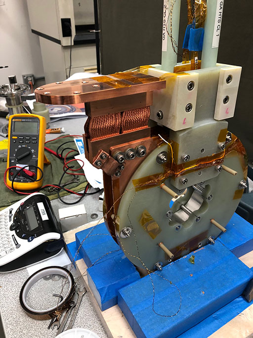
The completed magnet has a 10-cm inner diameter, 20-cm outer diameter, and was wound with a conductor tension of ~50 N, using winding equipment and technician support from Energy to Power (E2P) Solutions of Tallahassee, FL, as shown in Figure 2.
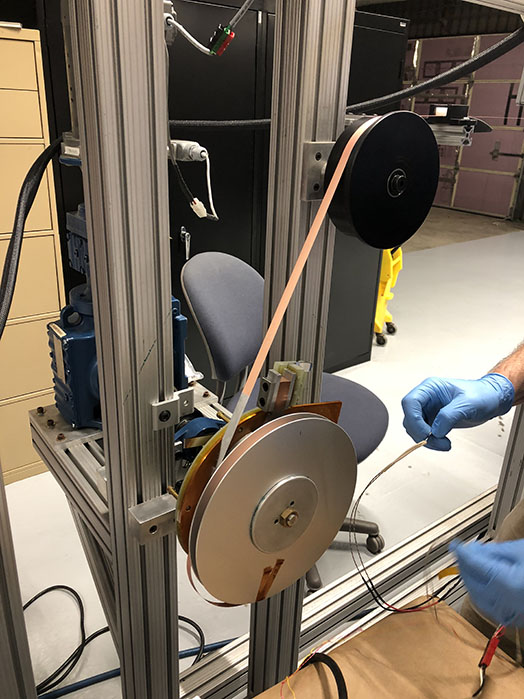
The winding system has electronically controlled winding speed and conductor tension. A tension force of 45 N was selected. This is within the allowable level for the conductor size, and ensures no liftoff of the conductor from the winding bobbin under the maximum operating conditions, since liftoff could result in a quench or mechanical damage.
The winding proceeded relatively smoothly. The main challenges were associated with ensuring the uniformity of the conductor tape. Since the tape thickness is only 0.1 mm, it was quite difficult to discern thickness uniformity across its 12-mm width on a single tape. After winding about 50 turns, it was discovered that the conductor was thinner on the edges by about 0.006 mm compared to the central section. To adjust for this difference in thickness, the edges were intermittently shimmed in the radial direction with polyimide tape.
After depositing about 20 turns past the first splice, it was discovered that the second section of the conductor tape was narrower by ~0.1mm. This led to the formation of a step on the face of the coil pack. Leaving the step in place would have resulted in a lack of lateral support in this section of the winding, which would further lead to mechanical damage to the conductor. In addition, because the magnet is conductively cooled from chill plates clamped on the end-faces of the magnet, the clamping force would not be constant in places where the tape was narrower, creating a thermal deficiency for cooling and causing potential damage to the conductor from the uneven clamping force.
To overcome this issue, lateral shims made of thermally conductive polyimide tapes (Kapton MP) were introduced to even out the surface and assure a good thermal path and lateral mechanical support. It was demonstrated during testing that the radial and lateral shimming with proper shimming material did not reduce the performance of the magnet.
The completed coil provides magnetic flux density greater than 6 Tesla on-axis within the 4-cm warm bore when operated at 4K-15K. It is one of the first in the world for a conductively cooled HTS magnet operated at high current (up to 700 amperes). Figure 3 shows a close up of the bore.
Applications
At the start of GA’s HTS magnet program, the goal was to develop engineering for HTS magnets, demonstrate the critical elements of fabrication, and test magnet performance using immersive cooling to 4K, without a specific application in mind. However, a very appropriate application arose even before fabrication was started.
Developing materials capable of surviving the intense neutron flux produced by fusion is one of the key challenges of associated with energy production from magnetic fusion reactors. There are no existing materials that can withstand this neutron fluence over the life of a commercial fusion power plant.
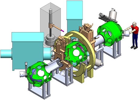
Researchers at the University of Wisconsin (UW) Fusion Technology Institute have been developing a device known as a gas dynamic trap (GDT) that is capable of simulating the fusion environment and can be used to qualify sufficiently robust plasma-facing materials. The GDT concept was first developed at the Budker Institute for Nuclear Physics in Russia. It comprises a long, axially symmetric, high-β, magnetic solenoid pinched by high-field mirror magnets at both ends, inside which a fusion plasma is confined. The UW machine, called the Wisconsin HTS Axisymmetric Mirror (WHAM), will also have applications for medical isotope production.
During the design phase of GA’s HTS magnet program, researchers from UW approached GA regarding the development of a small warm-bore magnet capable of producing a 6 Tesla magnetic field on axis for the WHAM experiment. Though GA’s HTS magnet was engineered to deliver the requisite magnetic field, the original immersive cooling method would not have been compatible with the UW experiment. In part because of the close alignment between the UW research and GA’s overall fusion program, GA decided to explore UW’s experiment as an application for the HTS magnet.
As an alternative to immersive cooling, GA engineers at the MTC examined the possibility of a conductively cooled magnet that would employ cryocoolers. With additional engineering design and analysis, it was determined that conductive cooling was feasible and would maintain the coil magnetic performance. However, this required re-designing the magnet to handle the high heat generation in the non-superconducting section of the bus bars, given the high (700 amp) current. In the previous design, the heat generated was extracted with immersive cooling, and switching to conductive cooling with cryocoolers presented a challenge because of their limited cooling capacity.
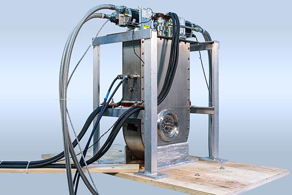
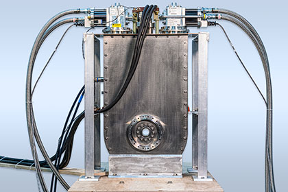
To have sufficient cooling power, two cryocoolers RDK415D and RDK400B were selected to extract the conductive and electrical heat losses. Both cryocoolers and their compressors were provided by Sumitomo Heavy Industry (Figure 4). Other design changes were made to improve the thermal coupling of the leads to provide the requisite cooling.
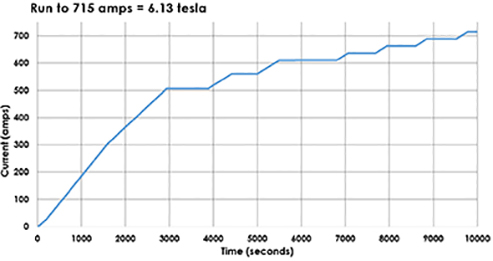
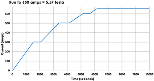
The completed GA HTS magnet with conductive cooling was tested at 4K in the fall of 2019. Figure 5 shows the results of one operational cycle. The magnet current was increased stepwise at rates of 0.3 A/s up to 500 A and 0.1 A/s from 500A–700 A.
The functional stability and safety of the magnet and supporting equipment, including the power supply, data acquisition, and quench protection systems were demonstrated through 104 hours of operation at 680 A. In addition, the magnet demonstrated safe discharges and quenches from the high current and field operating points.
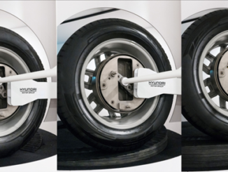
The GA HTS magnet, because of its high field and relatively large warm bore, has been demonstrated as ideal for the WHAM application (Figure 6). GA is working with UW to loan the magnet for UW’s experiment in late 2020.
GA is also exploring other possible applications. The positive features of the HTS magnet design – stable high field, relatively large warm bore, compact foot print, conductive cooling, ease of mobility, rapid fringe field decay, and automated quench protection – suggest similar magnets could also be useful in a variety of other fields. These include energy science, condensed physics, medical devices, microwave devices, material control applications, semiconductor crystal processing, scientific instruments, and defense applications.
—Dr. Zbigniew Piec is research scientist and Thomas W. Overton* is science editor, at General Atomics in San Diego.
*Contact author:
General Atomics Energy Group
858.455.2231
thomas.overton@ga.com
3550 General Atomics Ct.
San Diego, CA 92121