ABB is implementing a valuable way to conduct transient simulations of transformers. By integrating thermal-electromagnetic finite element analysis (FEA) with an electrical circuit model, engineers have an advantage to simulate and develop complex electric and magnetic devices.
Every so often processes need to be updated and improved. The design of current transformers, which are used to measure the electrical current in power distribution and control systems, is no exception. Many factors can cause deviations from a transformer’s expected performance: material properties, design constraints, and different loading conditions can all have a strong impact. In such situations, finite element analysis (FEA) makes all the difference.

As senior principal scientist of ABB Corporate Research Center Rolf Disselnkötter describes, “Finite element analysis is a powerful means of investigating the way in which external electrical sources and loads interact with a magnetic subsystem like a transformer core.” There are several elements to consider in the analysis of a transformer, and according to Disselnkötter, “FEA illustrates the transient behavior of these cores and the generated flux density distributions. It also elucidates the self-heating and effects of temperature-dependent material properties that need to be taken into account.”
Disselnkötter, alongside engineers from the University of Dresden, has been using Comsol Multiphysics to develop various modeling techniques. Because the models already combine 3D geometry, magnetic non-linearity, and transient analysis, coupling different physics is very challenging.
Modeling Design Details
Disselnkötter explains, “We are interested in how geometrical design variations, material properties, primary current distribution, temperature, and the electric circuitry will impact the accuracy of the electric current measurement. In order to allow for easy modifications and subsequent optimization procedures, we use parameter-based 3D model geometries.” In order to plan for various situations, the team introduced a potential problem into the design.
They added small air gaps to the transformer’s core to learn about the effects these would have. It was expected that the air gaps would induce demagnetizing fields and change the interactions between the transformer’s windings. The test model includes a ferromagnetic core that connects through coils surrounding the primary winding. The model allows transient finite element analysis of transformers that are integrated with models of external circuitry.
Apart from the deliberate air gaps, this is a typical transformer. Its primary winding is made up of one turn (a bulk bus bar) and the secondary winding consists of multiple turns which are arranged on two coil bobbins. The magnetic system is described by Ampère’s circuital law and by Faraday’s law of induction. For the core material, a nonlinear relationship between the flux density B and the magnetic field H of the type H = f(|B|)•B/|B| is assumed. Because of this, ABB needs a time-dependent simulation to model the electrical signals precisely. The air gaps lead to an asymmetrical geometry and cause an imperfect coupling between the primary and secondary windings.

Integrating FEA with a Circuit Model
According to Disselnkötter, “We built the circuitry from the predefined components provided with Comsol Multiphysics rather than importing it as a SPICE netlist. The coupling with the magnetic model was then implemented with equations for the currents and voltages on the two sides of the transformer.” The Electrical Circuit interface available in Comsol Multiphysics provided Disselnkötter with the equations for modeling his electrical circuits and solving for the voltages, currents and charges associated with circuit elements interacting with the FE model. At the primary side, the model is coupled to a sinusoidal current source, and at the secondary side it is coupled to an external load resistor.
Taking Eddy Currents into Account
Both the electrical losses and the magnetic field distribution will depend on the current density distribution in the conductors. An electric current alternating at high frequency will induce a time-varying magnetic field, and in turn an electrical field responsible for the creation of eddy currents. The team wanted to include eddy currents in their simulation and therefore be able to modify the current distribution in the conductors. “Modeling this is a bit tricky,” Disselnkötter explains, “as it is not the external current but the resulting total current that needs to be coupled to the circuit. In bulk conductors, like the primary bus bar of our model, the total current will be much lower due to the counteracting eddy currents. We therefore used a global equation approach to ensure that the total primary current follows the predescribed sinusoidal time course.”
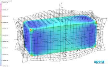
Taking this into account, the model computes the space- and time-dependent eddy current density in the primary conductor, and the resulting flux density distribution in the magnetic core; simulation results are shown in Figure 3. As Disselnkötter explains, “This is important for a precise calculation of the current error and the losses incurred by our non-ideal transformer.”

Transient Thermal-Electromagnetic Simulation
The team also wanted to take heat transfer into account. The thermal model incorporates heat conduction in the included solid materials as well as external convection on surfaces by means of convection coefficients. Comsol Multiphysics was also used to build the thermal model.
In general, electrical and magnetic material properties are temperature-dependent, so the effects of self-heating needed to be considered.
To address self-heating, the electromagnetic finite element model (FEM) was fully coupled to a thermal finite element model of the assembly. In most applications, however, the time scales of the electromagnetic and the thermal model are very different, so the team decided to simulate each model and couple the results until they reached convergence. The homogeneous temperature field was used as input for the first time-dependent study step of the electromagnetic model. After three or so simulated current periods, the time-averaged local power loss density was obtained as a new input to the thermal model. In the thermal simulation, the new temperature field was calculated and used as input in the electromagnetic model. The solutions converged within five iteration loops, leading to an even temperature distribution.
The team is continuing to improve this process. According to Disselnkötter, “We are looking for more accuracy and need to include further details, like the effects of the transformer core lamination and the anisotropic structure of the coils. In order to check the validity of the models, we plan to compare simulation results with accurate measurements on real magnetic components.” ABB is implementing thermal-electromagnetic finite element analysis to refine this process. When it comes to transformer design optimization, the more reliable the models, the better the design.
The Comsol Group provides software solutions for multiphysics modeling. The company was founded in July 1986 in Stockholm, Sweden. Comsol now includes offices in Denmark, Finland, France, Germany, the Netherlands, Norway, India, Italy, Switzerland, the United Kingdom and the US. For more information visit www.comsol.com.


