Electronic switching operations on the printed circuit board cause electromagnetic interference. Reducing these at the point of origin is the best method, but not always possible. Various factors such as the structure of the electronic assembly, the housing, but also the correct selection of the connector and the peripheral cable ensure EMC compatibility.
There are two types of electromagnetic interference – those that can enter a device from the outside and cause it to malfunction, and interference that is emitted by the device. By law, a device must have a certain intrinsic immunity in order to withstand a minimum level of electromagnetic interference. It is also only allowed to emit a limited amount of electromagnetic interference over cables and radiate a limited amount of electromagnetic waves. The correct interaction of the cable, the connector, the interface filter and the associated ground system are of particular importance here.
Radiation of electromagnetic energy via peripheral cables
The purpose of cables is to conduct an electrical signal from one location, the signal source, to another location, the signal sink. However, how the signal is transmitted depends on many influencing factors, such as the signal parameters and the system impedances as well as the properties of the cables and the shielding properties of the housing. All these points affect the radiation properties of the cable, but also its immunity to external interference.
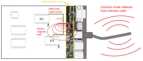
The coupling of interference between cables or of interfering circuits via the interface into the cables are two common and well-known phenomena. There are other types of coupling that occur mainly on the electronic assembly and are caused by mutual inductances or capacitances. This coupling is called crosstalk. Over 90 percent of the RF energy radiated by cables is caused by push-pull interference from the electronics, which is then radiated through the cable in the form of common-mode interference. Figure 1 (above) illustrates this “coupling mechanism”. One way to reduce coupling is to analyze the useful or interference signal, because the size of the coupling depends largely on the frequency spectrum and the current of the signal.
Clean signal integrity for interfaces
If a concept is selected via an interface connector, the result is a much better constellation. The connector can create a low-impedance connection to the surge limiting component due to its multiple ground connection between the housing wall and the PCB. However, the prerequisite is that the surge limiting component is placed close to the connector and that there is a low-impedance conductive connection between the connector housing and the housing wall. Figure 2 shows the structure.
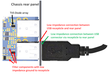
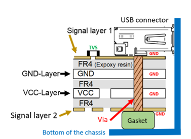
A prerequisite for a good ground connection is a high conductivity of the housing rear panel. If the material of the rear panel causes a high contact resistance due to surface treatment (painting, passivation, anodizing), the filter capacitors and the voltage-limiting components lack the ground reference. The corresponding filter effect against RF interference is missing, and transient interference, coupled into the interface cable, is conducted directly into the electronics. An improvement in mass by an additional conductive seal to the base plate, as shown in Figure 3 , can remedy this.
RF interfaces for coaxial connectors
Coaxial cables are used to transmit high-frequency electrical signals with low losses. However, these RF signals are “EMC-sensitive” – whether because of the radiation or because of the coupling of interference signals due to very small signal amplitudes. The prerequisite for the functionality of these interfaces is not only a high shielding attenuation of the connectors and cables, but also the adaptation of the entire signal path to the system impedance.
One hundred percent equality of impedances, i.e. one hundred percent adaptation, cannot be achieved in practice. There are still misadjustments, which also depend on the “quality” of the layout, among other things. Even if the connector, cable, and trace have the required system impedance, the transitions from one section of the system (e.g., trace) to another often cause mechanical problems that lead to mismatches. Another point that requires special attention is the ground reference of the various system sections: The reference ground for the signal source is the printed circuit board, as well as for the conductor path to the connector at the interface.
Influence on cable radiation
If you look at the overall system, i.e. the device, the factors such as the signal parameters and the impedance of the interference source play just as much a role as the “antenna” or radiation characteristics of the cable. In the frequency range from about 30 MHz to 300 MHz, radiation coupling is dominated by cable emissions rather than direct radiation from the electronic assembly. The electromagnetic properties of the environment (around the device) should also not be underestimated. In addition, the connector has a major influence on the radiation characteristics of a shielded cable, as it largely determines the impedance of the ground connection.
Another property that contributes significantly to the “radiability” of a cable is the relationship between the wavelength of the interference signal and the electrical length of the cable. The wavelength decreases with increasing frequency. When the wavelength gets smaller, the cables appear electrically long, which means that multiple wavelengths can fit into the cable length, and the cable acts as a sensitive antenna.
What distinguishes coaxial cables?
There is no cable that complies with the “EMC limits”, but there are cables with frequency-dependent shielding attenuation and a defined impedance. In addition to the fact that the quality of the cable is a high priority, the shielding of a cable must cover the entire length and circumference. In addition, this cover must have a high conductivity and should not have slots or openings. The problem with shielded cables is that, on the one hand, external interference must be kept on the outside of the shield braid (skin effect).
On the other hand, coaxial cables require a continuous “shielding sleeve” that is as low-loss as possible over the entire length in order to build up a counter-inductance between the center conductor and the shielding sleeve, which justifies the wave resistance and the shielding property as such. This is the only way to transmit the signal transported in the coaxial cable with the lowest possible losses and reflections. That’s why professional coaxial cables are stiff and thick. For flexibility, braided shielding is used in most cases. However, the shielding properties of the metal mesh are not as good as those of solid pipes and affect the linearity of the impedance over the frequency.
Coax Connector Requirements
When it comes to reducing EMC problems, it is often not the cable that is the cause, but often the connector. In the case of shielded or coaxial cables, the connector has two main tasks to fulfill:
- Connect the cable shield to the housing with as low an impedance as possible.
- Maintain the impedance of the cable.
Any deviation from the ideal state of the two points will lead to problems with signal integrity and EMC. If, for example, it is not possible to establish a low-impedance connection between the cable shield and the housing due to poorly connected cable shields or too high contact resistances between the connector and the housing, the use of a “better” cable has no effect on EMC and/or signal integrity.
This is because the interference current flows through the shielding of the cable. Typically, only about 3 μA of interference current is required through a 1 m cable shield to exceed the emission limit of the interference field strength according to CISPR 32. When the return current passes through the total impedance of the connector, cable shield terminations, and enclosure terminals, it creates a voltage drop, and this voltage between the enclosure and cable shield generates the current on the cable, resulting in interference radiation. This is shown in Figure 4 .
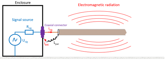
The parasitic inductance Lpar means that the return current at the connector is not perfectly symmetrical to the signal current. Any asymmetry in the coaxial cable causes the magnetic field lines of the signal current and the return current in the cable not to cancel each other out completely, creating a certain “stray inductance” that results in a “net signal current”; the portion of the signal stream that is radiated through the cable shield.
It is clear that connectors suffer from the same EMC problems as cables, after all, they are just short conductors in a rigid housing. Therefore, the overall design of the device is crucial not only for compliance with EMC requirements, but also for good signal integrity and therefore for a good product. Ultimately, cable connectors should have shielding properties that do not interfere with the shielding of the cable. With its WR-SMA product family, Würth Elektronik eiSos offers coaxial connectors designed for various applications.
Connection to the housing
Thus, the connector with its shielded cable represents an electromagnetically closed unit that must be contacted with the housing. It is also important to contact the entire circumference of the connector with a highly conductive, corrosion-resistant surface with no gaps. Why? The mass of the useful signal and the connector must be at the same potential in terms of RF technology. A metal housing establishes such a potential reference and also protects the electronics from direct field coupling from the outside.
In addition, a metal package provides a low-impedance RF grounding reference through the metal layer. The ideal housing must enclose the electronics on all six sides seamlessly and without openings. In addition, the minimum thickness of the material depends on the parameters frequency and field strength of the signal to be shielded. In practice, however, it is often not possible to achieve continuous shielding in all dimensions around the circuit – compromises have to be made.
By Dr. Heinz Zenkner, Technical Marketing EMC Consultant from Würth Elektronik eiSos


