By Robert Kaczmarek – Cobham Technical Services – Vector Fields Software
This article is intended to look at the implementation of electromagnetic Finite Element Analysis in a real world problem in order to gain insights and best practices around this type of analysis. In order to do so we have taken the published results of the Toyota Prius motor by Oak Ridge National Laboratory (ORNL) papers [1]-[5] and compiled a simulation based upon them. Through this process there were various challenges and ultimately lessons learned that can be translated into various different areas of Computer Aided Engineering. While both 3D and 2D analysis were run we detailed the 2D analysis in this article.
For this simulation we used Opera Machines Environment by Cobham Technical Services – Vector Fields Software.
 Motor Characteristics – The 2004 Toyota Prius Hybrid Vehicle uses a three phase, 48 slots, embedded permanent magnet motor with eight poles. The windings are distributed, single layered with nine turns per slot and connected in series.
Geometric Dimensions – The external diameter of the stator is 269.24 mm and the stack length is 83.56 mm. The resulting air gap for the Prius PMSM is 0.75 mm.
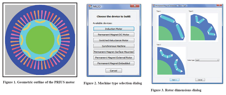
The V-shaped magnets are housed in specially designed rotor slots that aim to increase the quadrature-axis reactance in order to improve the motor’s performance. The air regions at the top of the magnet cutaway are designed to narrow the flux bridge in order to further increase Xq, as seen in Figure 1.
Magnetic Characteristics – The material used for the stator and rotor cores definition is M19 laminated steel based on the magnetic data provided by the manufacturer. The permanent magnets are characterised in the ORNL paper [1] and the BH curve used in the modelling is obtained by interpolating the measured points. However, these do not explicitly match the materials used in the real motor, which most likely accounts for the slight difference between measured and simulated data.
Measured Data – The tests published by ORNL cover a wide range of mechanical, electromagnetic, thermal and energy efficiency characteristics. The purpose of this application note is to compare the electromagnetic characteristics of the ME2D model against the ones produced by the real motor. Therefore, only the electromagnetic tests of the traction motor are considered in the following comparisons.
Analysis – The Finite Element Analysis was entirely done within Opera Machines Environment by Cobham Technical Services – Vector Fields Software in both 2D and 3D.
Opera Machines Environment 2D – The 2D Machines Environment is an automated toolbox that aids in the design of electrical machines within Opera FEM software.
After opening Opera’s Machines Environment the type of electrical machine needs to be selected from the list. In this case, the Permanent Magnet Embedded machine is selected (Figure 2).
In the Permanent Magnet Embedded dialog we selected the Default Values and then selected rotor Type 2 (Figure 3), as this type of rotor offers the V-shaped magnets needed for the Prius motor. Next, the rotor dimensions needed to be inserted.
The position of the magnets in the rotor is defined by the distance from the center of the shaft to the intersection of the two magnets.
The air region at the top of the magnets has a triangular shape in the default rotor definition. Further adjustment to the geometry of this region needed to be done in order to precisely model the real geometry and the optimized bridges near the air gap.
The default indents in the Permanent Magnet Embedded model are symmetrical and situated between the two V-shaped magnets. In the case of the Prius motor the indents are situated in a different position and are asymmetrical, thus they needed to be set using a customized rotor file.
At this step, the default indents were neglected by setting their depth and angle to zero.
Next, the stator dimensions are specified. As the geometry of the stator defined in the default machine model offers a square slot bottom, the stator will also undergo a further customizing. The winding used for the Prius model is distributed, single layer as seen in Figure 4.
We then selected create model and the application created geometry consistent to what was specified (Figure 1). Because of the unique geometry of the Toyota Prius Motor we had to then run a customization process for this model to insure 100 percent adherence to the complex geometry provided by ORNL.
Model Customizing – In addition to the pre-defined stator and rotor geometries provided by the 2D Machines Environment the user has the possibility of using a custom built geometry, both for the stator and/or for the rotor or to modify the geometry provided by the environment. We took full advantage of this feature and utilized a modification script that took all of about 15 minutes to create. The modifications made on a section of the machine are automatically replicated on all of the motor sections without the need for further intervention from the user.
When the modifications have been completed, the environment then proceeds to the meshing of the model. For the Prius model, both the rotor and the stator need minor alterations in order to match the complex geometry of the real motor (Figure 5).
Analysis – The cogging torque, static torque over a range of currents, and continuous torque were compared in this analysis and we therefore used two of Opera’s analyses: DC_ST and AC_ST.
The first analysis to be run is a DC_ST analysis, over 15° with a fine step, in order to obtain the cogging torque in the motor. Note that, as the cogging torque is obtained from a non-exited case, there is no need for a current to be given at this step.
The next analysis, the static torque vs. angle for a range of currents, will also use the DC_ST analysis. The simulation step can be coarser in this case and the analysis is done over 90°.
The Advanced Options dialog in the Meshing Parameters section gives the user the possibility to modify the default values of the scaling coefficients for all the regions of the machine. Here one can see an eighth of the periodic model meshed in Figure 6.
The continuous torque is the next analysis that is run and utilizes the AC_ST analysis. The simulation was run at the rated speed (3,000 rpm) for a given current (250 A)
Finally, a rotating machine (RM) analysis is run in order to obtain the transients of the PRIUS motor and to verify the back-EMF results obtained from the previous analysis.
Results – The cogging torque produced by the motor’s geometry, over two stator poles, is presented in Figure 7.
The static DC torque was computed for currents ranging from 50 A to 250 A. The measured current data from ORNL is overlaid on top of the FEM results. As seen in (Figure 8). Note the slight difference is likely the cause of the approximations made of material properties and exclusion of the effects of the end windings.
A second analysis is conducted at rated speed and 250 A using the AC_ST analysis. The starting angle is 22.5°, which is the peak torque position obtained from the DC_ST analysis. The steady state torque is presented in Figure 9. The back-EMF results obtained for this machine are shown in Figure 10. The comparison with the measured results is presented in Figure 11.
For a more detailed write up on the Toyota Prius Motor visit www.operaFEA.com.
 About the Author
Robert Kaczmarek has more than 10 years of experience in bringing innovative CAE applications and processes into various industries and has worked with the likes of Lockheed Martin, Boeing, Halliburton, General Electric, John Deere, BMW, General Motors, Renault F1 racing team, Oracle Team USA racing, and countless others. He brings his unique skill set to address the countless challenges inherent in electric machine design.
References
[1] Hsu, J.S.; Ayers,C.W.; Coomer, C.L.; Report on Toyota/Prius motor design and manufacturing assessment, Oak Ridge National Laboratory, July 2004, ORNL/TM-2004/137
[2] Hsu, J.S.; Ayers, C.W.; Coomer, C.L.; Wiles, R.H.; Campbell, S.L.; Lowe, K.T.; Michelhaugh, R.T.; Report on Toyota/Prius motor torque capability, torque property, no-load back emf and mechanical losses, Oak Ridge National Laboratory, September 2004, ORNL/TM-2004/185
[3] Ayers, C.W.; Hsu, J.S.; Marlino, L.D.; Miller, C.W.; Ott, G.W.; Oland, C.B.; Evaluation of 2004 Toyota Prius hybrid electric drive system interim report, Oak Ridge National Laboratory, November 2004, ORNL/TM-2004/247
[4] Hsu, J.S.; Nelson, S.C.; Jallouk, P.A.; Ayers, C.W.; Campbell, S.L.; Coomer, C.L.; Lowe, K.T.; Burress, T.A.; Report on Toyota Prius motor thermal management, Oak Ridge National Laboratory, February 2005, ORNL/TM-2005/33
[5] Staunton, R.H.; Ayers, C.W.; Marlino, L.D.; Chiasson, J.N.; Burress, T.A., Evaluation of 2004 Toyota Prius hybrid electric drive system, Oak Ridge National Laboratory, May 2006, ORNL/TM-2006/423
[6] ME2D User Guide, Cobham Technical Services, 24 Bankside, Kidlington, Oxford, OX51JE, UK
Reprinted from the Spring 2013 Issue of Magnetics Business & Technology


