Co-authored by Lawrence Livermore National Laboratory and Arnold Magnetic Technologies
A Collaboration Between Lawrence Livermore National Laboratory and Arnold Magnetic Technologies takes Passive Magnetic Bearings from Theory to Hardware
Magnetic bearing/stabilizer systems have many advantages over conventional mechanical bearing systems. These include near-zero drag losses and no need for lubrication since the rotating elements make no mechanical contact with the stationary elements of the bearing system. However, all magnetic bearing systems must contend with a constraint known as Earnshaw’s Theorem. Derived in the early 1800s, this theorem asserts the impossibility of constructing a stable, non-contacting, electrostatic or magnetostatic levitation system using only fixed charges or fixed magnetic poles, such as those produced by permanent magnets. Because of the constraint imposed by Earnshaw’s Theorem virtually all present-day commercial magnetic bearing systems are of the “active” type. That is, they employ electromagnets that are powered by amplifiers the inputs to which come from sensors embedded in the bearing system. These sensors are a part of a feedback loop that operates to keep the levitated rotating parts of the bearing stable and centered. The resulting complexity means that active magnetic bearings are expensive, require periodic maintenance, and continuously consume electrical power to energize their amplifiers and their electromagnets.
Passive magnetic bearings are, of course, also subject to the constraints imposed by Earnshaw’s Theorem but they solve this problem in a straightforward and simple way, with only “passive” elements that take advantage of a loophole implicit in the derivation of Earnshaw’s Theorem. This loophole is that Earnshaw’s Theorem as derived applies only to static systems, i.e. an assembly of stationary permanent magnets arranged so as to levitate an object containing other permanent magnets. The theorem can be overcome if dynamic effects are taken into account. In active magnetic bearings the dynamic effects involve the afore-mentioned sensors, amplifiers and electromagnets.
Passive Magnetic Bearing Systems and the Halbach-Array Stabilizer

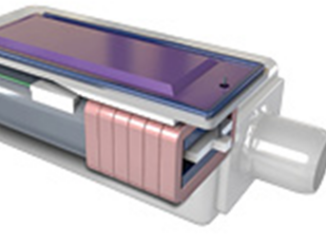
Is it possible to build a magnetic bearing that is passive in nature? That is, a magnetic bearing that requires neither sensor-controlled electromagnets nor an external source of electrical energy. If so, can it be designed to be maintenance-free for their lifetime, which should be measured in decades, there being no components that are subject to wear during normal operation? Livermore Laboratory’s passive bearing systems involve levitating permanent magnet arrays plus a stabilizer of the type described in this report. The stabilizer, as shown in Image 1, is simple in form, consisting of an upper and a lower Halbach [1] array. (An array of permanent magnets that produces a magnetic field near the front surface of the array that varies periodically in azimuth. These magnets are coupled mechanically to, and rotate with the levitating magnet arrays.)

Between the two arrays there is a stationary winding, usually shorted electrically at its ends. By design, the two Halbach arrays are oriented so that the vertical component of their magnetic field cancels at the mid-plane between them. When the passive bearing system is rotating under these conditions no current is induced in these windings, and their losses approach zero. Only when the rotating arrays are displaced up or down with respect to the mid-plane is current induced, and together with the current a strong restoring force is generated. This type of Halbach-array stabilizer [2,3] is thus described as an axial stabilizer. To complete the picture, the accompanying levitating permanent-magnet arrays are designed so as to be intrinsically stable against transverse displacements, and therefore the Earnshaw unstable displacement is an axial one, now stabilized by the Halbach stabilizer. Also, since the LLNL passive bearing technology employs dynamic effects associated with rotation, some form of touchdown bearing is required to come into play when the system is not rotating. This bearing also can act to protect the system from the effects of seismic or other high-acceleration events.
Building the Prototype Stabilizer
Based upon the theoretical design, LLNL created a 3D model and ultimately mechanical drawings to manufacture a prototype stabilizer. The drawings were reviewed in a joint session between LLNL and Arnold to make ease-of-manufacturing and assembly improvements that lead to a final set ready for manufacturing.

The prototype design involved two highly precision-machined plates, each 19 inches in diameter, which encased magnetic Halbach arrays along with other assembly components. The permanent magnets in these arrays were made of high magnetic field strength material and precision ground to tight tolerances in custom shapes order to fit into the machined slots in the plates. For accurate testing, it was required that there were no air gaps and that the radial timing of the individual magnets from plate to plate was accurate.
Due to the strong interaction of the individual magnetic fields, the placement of the high strength magnets that created the Halbach array in the plate support structure proved to be the most challenging portion of the assembly. The magnets, each with its own angle of orientation, were fabricated at Arnold and assembled into the plates to ensure correct phasing to achieve the proper overall magnetic field orientation. They were positioned using precision custom designed tooling and held in place with applicable adhesives to withstand the calculated forces and temperatures.
Once the plates were completely assembled with the high-performance magnets properly inserted, they were individually tested to ensure the final magnetic field profiles were correct. They were securely mounted to a rotating table and a gauss probe was positioned approximately 0.125 inches above the top surface of the magnet array. The plate was rotated and the magnetic field was recorded. As seen in Graph 1, the Halbach array created a sinusoidal magnetic field which when the plates are opposed and properly timed will create the null field of the stabilizer.

In the final assembly, the plates face each other and are aligned such that opposing magnetic fields create a central equilibrium plane between them. As described previously a stabilization force is created in this region. Understanding the interactions between magnetic fields is essential in designing the magnet array to achieve the desired magnetic field strength and orientation. Once the individual components were completed, they were sent to LLNL where they were assembled and tested.
Testing of Stabilizer Up to 1,000 RPM
Initial testing of the stabilizer at LLNL has yielded results that confirm the predictions of computer codes developed at LLN, codes based on theoretical analyses. The basic theory behind these codes was derived in connection with earlier work on a new type of magnetic levitation system, the Inductrack [4]. These earlier codes were benchmarked against experimental results, confirming the validity of the theory. In addition to the LLNL code results a Halbach stabilizer code developed independently at Carnegie-Mellon University in Pittsburgh by Professor James Hoburg gave almost identical results. This latter development came about because of a Lab-sponsored collaboration between LLNL and Carnegie-Mellon in support of a Laboratory program, which involves the use of passive magnetic bearings

The initial testing, limited to rotation speeds at or below 1,000 rpm by technical considerations, gave encouragingly close agreement with both the LLNL and the Carnegie-Mellon codes. An example of the agreement between experiment and theory obtained with the LLNL code is shown in Graph 2. This plot compares the theoretical prediction of restoring force versus displacement of the rotating stabilizer magnet assembly from the “null” position at a rotation speed of 500 rpm. As can be seen the agreement between the code and experiment is satisfyingly close.
As is apparent from Graph 2, the restoring force for this stabilizer at 500 rpm is steeply rising with rotation speed, aiming toward an asymptotic value at roughly 10 times this speed. The next plot shows the predictions of the code for the restoring force at a fixed displacement as a function of the rotation speed.
Note that it is possible to modify the parameters of Halbach Stabilizers so that the asymptotic value of the restoring force occurs at substantially lower rotation speeds than the present one. These parameters include the wavelength of the Halbach arrays, the diameter of the magnet arrays and the use of external inductances to short the windings.

Finally, we show plots of code results comparing the LLNL code and the Hoburg code indicating close agreement between for the cases shown. The plot of the LLNL code also shows experimental values obtained in the initial tests.
Brief List of Future Testing
Building on the results of this prototypes testing, there are many future tests set in place. The first set is to take the existing prototype to higher RPM’s and compare its actual results with the theoretical results to see if it is scalable for high speed applications. Another test involves adding another phase-displaced Litz wire winding in the stabilizer in order to increase the stabilization forces. And a final test is to incorporate this prototype into a complete passive magnetic bearing system to test the interaction between the levitation magnets and the stabilization portion.

Applications
Some examples of how magnetic bearings are used today, in limited quantity, are uninterruptible power supplies, such as flywheel energy storage systems and magnetic levitation transportation.
Other applications include, but are not limited to:
- Wind Turbines
- Steam Turbines
- Jet Engines
- Electric Motors
- Electric Generators
- Couplers
- Compressors
- Medical Devices

Advantages
Passive magnetic bearings have several advantages over electromagnetic bearings. For example, they do not require an external power source to run and have no active control circuits. Consequently they can be far less expensive and will not require periodic maintenance. Furthermore, they are far more efficient to operate than conventional bearings since they have near-zero drag losses.
Conclusion
First results from the testing of a Halbach stabilizer designed by LLNL and constructed by Arnold Magnetic Technologies have been described, along with comparisons between two independently developed computer codes (LLNL and Carnegie-Mellon University). Future experiments will aim at higher speed operation and at modifications of the present system that include an additional winding that is predicted by the codes to double the stabilizer stiffness. Completion of these tests will prepare the way for the design of Halbach stabilizers for a variety of possible applications of passive magnetic bearing systems of the type developed by the Lawrence Livermore National Laboratory.
References
[1] K. Halbach, Jour. Applied Physics, 57,3605 (1985)
[2] R. F. Post and D. D. Ryutov, Proc. of 6th International Symposium on Magnetic Bearings, Cambridge, Mass., Aug. 5-7,1998
[3] R. F. Post, U. S. Patent No. 5,495,221, Dynamically Stable Magnetic Suspension/Bearing System.
[4] R. F. Post, D. D. Ryutov, The Inductrack: a simpler approach to magnetic levitation, Proceedings of the Sixteenth International Conference on Magnet Technology, IEEE Transactions on Applied Superconductivity, Vol. 10, 901-904, 2000
About the Authors
Co-authored by Dick Post, Bob Yamamoto and Annemarie Meike from Lawrence Livermore National Laboratory, and John De Leon with Arnold Magnetic Technologies. This collaboration combines LLNL engineering expertise and retired LLNL inventor and physicist Richard Post’s many years of experience in magnetic theory and a large portfolio of resultant inventions with Arnold’s more than 100 years of industry experience and expertise in design and manufacturing of high performance magnets and precision magnetic assemblies.
Published in the Winter 2011 Issue


